

Adattamento di impedenza en
From "Physics, Waves, Music": a website about the physics of waves and sound, acoustics of musical instruments, musical scales, harmony and music.
| AI-translated from Italian. Original page: Adattamento_di_impedenza |
A model situation
The concept of impedance becomes particularly useful when we want to study the transfer of energy from one medium to another by exploiting the most characteristic property of waves, namely their ability to propagate. Informally, we can say that impedance is a physical quantity that concisely describes how much a medium "opposes" the propagation of waves. In the most general case, impedance is expressed as a proportionality coefficient and a phase shift relating two quantities whose product has the dimensions of work per unit time, such as force and velocity.

To be more precise we need to refer to an example, and we choose a case similar to the one illustrated in detail on the page refraction in one dimension (in Italian), namely the case in which a mechanical pulse propagates along two pieces of string of different density joined at a point. This particular case has no real practical applications, but it is especially well suited to illustrate the phenomenon. Applications are discussed in the next section.
So let us consider two ideal strings of densities ρ1 and ρ2, joined at a point and subject to a tension T. We send a transverse wave along them, as in the animation alongside. For an intuitive idea of how the phenomenon develops, see the animations and comments on the page refraction in one dimension (in Italian).
The specific impedance of the string is the quantity Z that relates the tension of the string to the propagation speed of waves along the string as follows
- .

Given the amplitude A of a wave propagating along the string, the energy the wave carries per unit time is
- .

We refer to the page on the impedance of a vibrating string for the full derivation of the mathematical expression of the impedance of the string, and focus here on the final result. For our two pieces of string we have
- ,
- .


Note that the lower the impedance of the string, the faster the mechanical wave travels along it.
We can now introduce the coefficients of transmission and reflection, which tell us the amplitudes of the transmitted and reflected waves, given the amplitude of the incident wave.
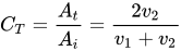
- The transmission coefficient is the ratio between the amplitude of the transmitted wave and that of the incident wave
- .
- The reflection coefficient is the ratio between the amplitude of the reflected wave and that of the incident wave
- .
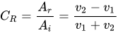
The full derivation of the coefficients, in terms of the propagation speeds in the two pieces of string, can be found on the page transmission and reflection coefficients.
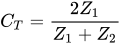
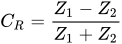
We can now express them in terms of the impedances by substituting the variables, and we obtain
. (1)
and
. (2)
The point of this substitution is not obvious at this stage, but it becomes clear immediately if, instead of focusing on the amplitude of the reflected and transmitted waves, we study the amount of energy transmitted and reflected by the junction per unit time.
Indeed, if we recall that the energy of a harmonic wave is proportional to the square of its amplitude (see energy carried by the wave and energy of the vibrating string), and call Ei, Er and Et the amounts of energy incident on, reflected by and transmitted through the junction respectively, we have
- ,
- ,
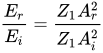
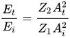
from which, substituting (1) and (2),
, (3)

. (4)
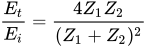
- Looking at the mathematical form of (3) and (4), we can see that if Z1 and Z2 are very different from each other, energy cannot be transferred efficiently from one medium to the other.
Indeed, both when and when , we have


- ,
- .


In other words, when two media have very different impedances, the energy, whichever side it comes from, is almost entirely reflected at the interface, and does not manage to pass into the other medium.

Looking at the graph of the ratio between Et and Ei shown alongside, we also notice that the energy transfer coefficient is always at its maximum when Z1=Z2, for any values of Z1 and Z2. Consequently, maximum transmission efficiency is obtained only when the two media have the same impedance. We also see that the maximum is rather "broad"; in particular, this means that, as the impedances grow, a good transfer only requires Z1 and Z2 to be "not too different".
Here, then, is the fundamental technological problem illustrated by our model situation:
- how can energy be transmitted between two media with very different specific impedances?
The answer is a technique known as impedance matching.
Matching and matching devices
The key idea is the following: insert between the two original media a third medium, with an appropriate impedance and size, such that the impedance of medium 1 joined to medium 3 is very similar to that of medium 2 or, equivalently, such that the impedance of medium 2 joined to medium 3 is very similar to that of medium 1. In our example the matching device is simply a piece of string of appropriate density and length.
The ideal matching condition is reached when the impedances of medium 1+3 (let us call it 1') and of medium 2 are identical, . When this happens, it is easy to see from (3) and (4) that

- ,

while
- ,

that is, the two media are "transparent" to each other, and all the energy is free to flow from the first to the second and vice versa.
Now that the transmission or reflection of waves between two media is expressed in terms of impedances, we can easily see that, through physical analogy, the same reasoning actually applies to many different fields. In each case the energy involved has a different expression, and so does the specific impedance of the medium, but the matching principle stays the same.
Mechanical and acoustic examples
- Mechanical impedance matching in musical instruments
Think of string instruments. When we hear their sound, it is carried by the air. However, the player does not excite the air directly, as happens instead with wind instruments. The player sets one or more strings vibrating, which in turn set a wooden surface vibrating (a board that is part of the body of the instrument), which finally acts on the air. We have a chain of three systems, each with its own specific impedance. In particular, the impedance of the strings turns out to be much lower than that of the board. So an impedance matching device is needed between the two. It usually consists of a wooden "bridge" over which the strings are stretched. The bridge receives the vibration of the strings and "levers" with its feet on the board, effectively matching the impedances of the two systems and allowing the board to be excited by the strings.
- Acoustic impedance matching between an ultrasound probe and the skin by means of a gel
The acoustic impedance of a medium is given by the product of the density of the medium and the speed at which sound propagates in it. Consequently, it is easy to see that air and water have impedances completely unsuitable for passing sound waves to each other, because the impedance of water is much higher than that of air (on this point see also the discussion of sound refraction). Indeed, ultrasound diagnostic equipment cannot send ultrasound to the patient through air: it needs an emitter placed in contact with the patient's body, and a gel to better match the impedances of the emitter and the human body. For the same reason, the internal cavities of the body that contain air are completely opaque to ultrasound, which is always totally reflected at the boundary between air and water.
The same argument applies to underwater acoustics, where it is important to match the impedances of emitters and microphones (usually made of steel) to that of water in order to send and receive sound signals through it.
- Impedance matching in the auditory system
As illustrated in more detail on the page on the anatomy of the auditory system, a problem very similar to the previous one arises in the conversion of acoustic energy into mechanical energy that takes place inside the ear. At the two ends of the transduction chain there are, on one side, the air, which carries the sound waves, and on the other the cochlea, which contains a liquid that is the last stage in which sound is still mechanical energy inside the human body. The vibration of the liquid excites hair cells, from which the signal no longer leaves as a mechanical oscillation but as an electrical impulse. The complex mechanism of membranes (eardrum), levers (ossicles) and muscles placed between these two ends is nothing but an elaborate impedance matching device that makes possible the passage of energy between the two media (air and cochlear liquid), which would otherwise be impossible.
Electromagnetic examples
- The quarter-wave anti-reflection coating on lenses (see the App Onde 2D en for an interactive simulation of the phenomenon).
This is a case of optical impedance matching. The waves and the energy involved are electromagnetic. The aim is essentially to reduce the optical reflection coefficient of a lens in a certain range of the spectrum (for example the visible). This makes the lens "more transparent" in that region of the spectrum. The technique is particularly important in astronomical telescopes, because it improves their efficiency and increases the contrast of the images. The matching device is a thin film applied to the lens, which produces destructive interference between the reflected rays. It can be shown that the impedance matching condition, when the film is a quarter (or an odd multiple of a quarter) of the wavelength whose reflection is to be eliminated, is
- ,

that is
- .
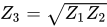
The same value (called the geometric mean of Z1 and Z2) can also be used for our string example in the first section. Of course the definition of Z changes, but not the matching condition!
- Microphone-amplifier, amplifier-loudspeaker matching, etc.
Any electrical circuit can ultimately be seen as a "box" with four terminals: two input and two output. Even without knowing exactly what the box contains, we can measure its input and output electrical impedances. When we want to connect one circuit to another, we simply connect the two output terminals of the first circuit to the two input terminals of the second. This is where our matching principle applies. Maximum power transfer occurs when the impedances are matched; if the connections are long compared with the wavelength, as in the cables carrying radio-frequency signals to antennas, a mismatch also produces reflected waves along the line. In audio systems, on the other hand (microphone-amplifier and amplifier-loudspeaker), one usually aims not at maximum power transfer but at signal fidelity: a low-impedance output is connected to an input with a much higher impedance, so that the signal voltage passes through almost unchanged.
